
Installazione guarnitura
Guida installazione guarnitura R7 Ø29mm
Required Tools
MechanicalGather the tools below before installing your WHALEROAD R7 Ø29mm alloy spindle crankset. Using incorrect tools may damage parts or compromise safety.
BB Tool
SRAM DUB compatible
Essential8 mm Hex Key
Tighten crank bolt
Essential2 mm Hex Key
Tighten preload ring bolts
EssentialTorque Wrench
2–60 N·m range
EssentialBearing Press
BB30 / PF30 compatible
Press-fitWaterproof Bicycle Grease
Thread lubrication
EssentialInstallation Steps
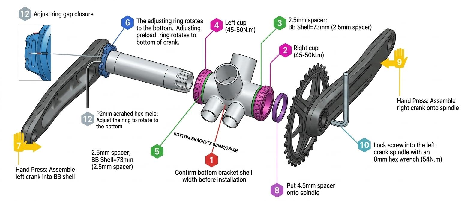
Confirm BB Shell Width & Type1
Choose the correct installation method and spacer layout based on your frame.
- ✓ Measure BB shell width
- ✓ Match BB model
- ✓ Clean shell faces
- Measure your frame's bottom-bracket shell width.
- Refer to the BB Specification Table below for the matching BB model and spacers.
- Clean the shell faces thoroughly—remove dirt, old grease, and paint residue.
Install the Right Cup (Threaded)23
The right cup has a reverse thread; tighten by turning counter-clockwise.
- ✓ Apply grease
- ✓ Counter-clockwise
- ✓ 45–50 N·m
- Apply a thin layer of waterproof bicycle grease to the threads.
- Thread the right cup into the BB shell using a SRAM DUB–compatible tool.
- Torque: 45–50 N·m.
Install the Left Cup (Threaded)45
The left cup has a standard thread; tighten by turning clockwise.
- ✓ Apply grease
- ✓ Clockwise
- ✓ Includes press-fit note
- Apply grease to the threads.
- Thread the left cup into the BB shell using a SRAM DUB–compatible tool.
- Torque: 45–50 N·m.
Press-fit alternative: For press-fit bottom brackets, press both cups in squarely with a BB30/PF30-compatible bearing press. Never hammer cups into the frame. Confirm compatibility with the BB spec table first.
Set the Preload Ring Position6
Before installing the crank arms, rotate the left preload adjuster fully to the bottom position.
- ✓ Locate preload adjuster
- ✓ Turn to bottom stop
- ✓ Don't tighten bolts yet
- Locate the preload adjuster on the left crank spindle.
- Turn it opposite to the arrow direction until it reaches the bottom stop.
- Do not tighten the fixing bolts yet; leave adjustment for after crank installation.
Install the Crankset78910
Insert the crank arms, add the spacer, and tighten the crank bolt.
- ✓ Insert crank arms
- ✓ 4.5mm spacer
- ✓ 180° apart
- ✓ 54 N·m
- Insert the left crank arm through the BB shell from the left side.
- Slide the 4.5mm spacer onto the right spindle (confirm against the spec table).
- Fit the right crank arm onto the spindle, ensuring the arms are 180° apart.
- Tighten the crank bolt with an 8mm hex key to 54 N·m.
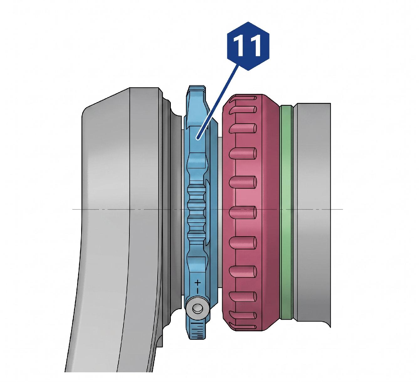
Adjust the Preload Ring11
Turn the preload ring in the arrow direction until play is removed.
- ✓ Follow arrow direction
- ✓ Contact dust seal
- ✓ Remove play
Turn the preload adjuster on the left crank spindle in the arrow direction until it contacts the bearing dust seal and the crankset no longer has play. Do not overtighten.
Tighten the Adjustment Bolts12
Secure the preload ring bolts with a 2mm hex key until the ring gap closes.
- ✓ 2mm hex key
- ✓ Ring gap closes
- ✓ Light torque only
Using a 2mm hex key, tighten the preload ring fixing bolts until the ring gap closes. A small gap is acceptable if the top edge touches the bearing dust ring. Do not overtighten—excessive force will damage the bolts or crank-arm threads.
The preload ring bolts need only light torque—excessive force will damage the bolts or crank-arm threads.
Final Inspection
Check the crankset for play after installation.
- ✓ Rock crank front-to-back
- ✓ Check for looseness
- ✓ Reinstall if needed
After completing all installation steps, rock the crankset front-to-back to check for play. If it is loose, remove the crankset, apply more waterproof bicycle grease to the spindle, and reinstall.
BB Spacer Specification Table
Spacer LayoutSelect the correct BB model for your frame. All measurements are in millimeters (mm); "—" means no spacer is required in that position.
| Application | BB Model | BB Type | Shell Width | Outer Left | Inner Left | Inner Right | Outer Right |
|---|---|---|---|---|---|---|---|
| Road / Gravel | BB-BSA29R | BSA | 68 | — | — | — | — |
| Road / Gravel | BB86-29R | PressFit | 86.5 | — | — | — | — |
| Road / Gravel | PF30-29R | PF30 | 68 | — | — | — | — |
| Road / Gravel | BB30-29R | BB30 | 68 | — | — | — | — |
| Road / Gravel | BB386-29R | BB386 | 86.5 | — | — | — | — |
| Road / Gravel | T47-68-29R | T47 | 68 | — | — | — | — |
| Road / Gravel | T47-77A-29R | T47 | 76.75 | — | — | — | — |
| Road / Gravel | T47-85.5-29R | T47 | 85.5 | — | — | — | — |
Critical Warnings
Exceed 54 N·m on the crank bolt—damage to the spindle or crank arm may occur.
Overtighten the preload ring bolts. Stripped threads will require crank-arm replacement.
If play cannot be eliminated after repeated adjustment, verify the spacer configuration against the BB table.
Inspect the crankset for looseness during the first 200 km of riding.
Important Notes
Keep these points in mind before and after installation for long-term reliability.
Confirm Specs First
Always confirm BB shell width and type before purchasing or installing the crankset.
Grease Threads
For threaded BB installations, apply a thin layer of grease to the cup threads.
No Hammering
Use a proper bearing press for press-fit installations. Never hammer BB cups into the frame.
Re-check Torque
Check crank bolt torque after the first ride and periodically thereafter.